
Ph.: +1-248-509-5000

Computer Aided Engineering (CAE)
MPI offers in-house Computer Aided Engineering services for OEM and aftermarket parts.
At MPI, Computer-Aided Engineering (CAE) plays a critical role in de-risking programs and accelerating development timelines. By leveraging advanced simulation tools, we evaluate manufacturability, optimize part and tool designs, and predict performance outcomes before any steel is cut. Our CAE workflows are fully integrated with design and tooling, allowing us to make informed decisions early—reducing iterations, avoiding costly rework, and ensuring production readiness.
We apply a range of simulation techniques tailored to each phase of development. Below is a breakdown of the core CAE services we offer and how each contributes to a more robust, efficient process:
Finite Element Analysis (FEA)
MPI applies FEA across several analysis domains to evaluate different aspects of part behavior. Each type provides critical insights into structural performance, thermal stability, and durability under dynamic loading:
Static
MPI performs linear and nonlinear structural simulations to predict how components respond to real-world loads, including stress, strain, and deformation. This enables us to assess material behavior under operating conditions and ensure structural integrity across a range of use cases.

Vibration
We use vibration analysis to predict a part’s response to dynamic loading and excitation across a range of frequencies. The results inform adjustments to geometry or material selection to mitigate resonance and improve fatigue performance.

Thermal
Our thermal simulations model steady-state and transient heat transfer, helping identify hotspots and thermal gradients that could affect part performance or dimensional stability. This is especially critical in applications where temperature plays a role in material properties or system behavior.

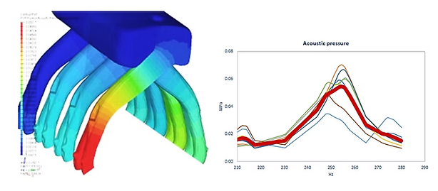
Acoustic
Acoustic simulations evaluate how sound waves interact with a component, quantifying response characteristics that contribute to overall system noise or tonal quality. This analysis supports refinement in environments where NVH performance is critical.
Computational Fluid Dynamics (CFD)
MPI utilizes CFD analysis to study flow behavior through a part or assembly. These simulations provide a visual representation of flow and cooling behavior, enabling improvements to flow paths and reductions in pressure drop.
Steady
Steady-state airflow analysis is used to evaluate flow behavior in air induction systems under constant conditions. This supports early-stage optimization of inlet geometry and flow uniformity.

Thermal Flow
Thermal flow analysis evaluates air temperature distribution through components such as intercoolers. The results inform design adjustments that improve thermal efficiency and system cooling performance.

Transient
Transient analysis models time-dependent airflow through the intake manifold while the engine is running. These simulations capture dynamic flow changes that impact performance under real-world driving conditions.

Flow in Rotating Reference Frame
This analysis simulates rotating airflow to assess fan performance and flow generation. MPI uses it to optimize aerodynamic behavior in components involving rotational motion.

Multi-Phase Flow
Multi-phase flow simulations evaluate the interaction between air and liquid as a mold tool fills. This helps identify trapped air pockets and improve fill consistency in complex geometries.

Moldflow
MPI uses Moldflow simulations to predict how thermoplastic materials behave during each stage of the injection molding cycle. These analyses allow us to identify and correct issues related to flow, temperature, fiber orientation, and part distortion.
MPI offers five distinct Moldflow simulation types, each addressing a critical phase of the molding process and informing decisions that improve manufacturability and dimensional accuracy.
Mold Filling
Fill analysis predicts thermoplastic polymer flow inside the mold during the filling phase. The simulation calculates how the flow front progresses from the injection location and continues until the switch-over point is reached.

Glass Fiber Orientation
The Fiber orientation analysis is used to predict the behavior of composite materials. The results from the Fiber orientation analysis can be used later as input for a Warp analysis, providing more detailed elemental results, and considerably enhanced analysis accuracy.

Gate Optimization

Cooling
The cool simulation analyzes both the temperature of the part and the temperature of the mold, calculating a cycle averaged temperature distribution in the mold, in order to optimize various aspects of the design of the part, including cooling time, cycle time, part design, and mold design.

Warp
Warp analysis is used to diagnose the cause of warping and recommend a solution, such as gate location changes, design parameter changes, or reduction of wall thickness variations.
