
Ph.: +1-248-509-5000

Computer Aided Engineering
Managed Programs offers in-house Computer Aided Engineering services for OEM and aftermarket parts.
FEA
Finite Element Analysis


Static
-
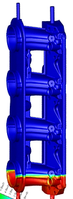
Burst analysis to evaluate the pressure resistance of the intake manifold, thermal deformation and gasket sealing.
-
Case study:
-
CAE Analysis : Failure at 7.5bar with initiation at the weld bead
-
Real World Test: Failure at 7.2-8.4bar, crack initiation at the weld bead – great correlation with the test result
-
Thermal
-
Thermal deformation analysis to evaluate how the part expands at high temperature.
-
Gasket sealing analysis to evaluate sealing pressure of the rubber gasket.
-
Temperature distribution analysis to evaluate uneven temperature distribution of the tool by hot water circulation.
Vibration
-
Resonance frequency, Vibration response analysis to evaluate vibration of the variable induction valve inside the intake manifold.
-
Vibration response peak frequency result – Good correlation with actual engine test.
Acoustic
-
Acoustic resonance analysis to evaluate acoustic pressure in the runner at resonance for tuning intake manifold performance.
-
Sound transmission analysis case study:
-
Evaluate sound attenuation performance of sound tuning devices.
-
Noise test result: High noise level frequencies correlated with the analysis result.
-
CFD
Computational Fluid Dynamics


Steady
-
Air flow analysis to evaluate air flow in air induction systems.
Transient
-
Air flow analysis to evaluate air flow in the air intake manifold with the engine running.
Thermal Flow
-
Airflow temperature analysis to evaluate the temperature of the air flowing through the intercooler.
Flow in rotating reference frame
-
Rotating airflow analysis to evaluate fan performance in terms of flow generation.
Multi-phase flow
-
Air and liquid flow analysis to evaluate liquid flow filling the tool to find trapped air.

MoldFlow
Injection molding flow simulation


Mold Filling
The Fill analysis predicts the thermoplastic polymer flow inside the mold in the filling phase. A Fill analysis calculates the flow front that grows through the part incrementally from the injection location and continues until the velocity/pressure switch-over point has been reached.
Gate Optimization
The Gate Location analysis is used to recommend injection locations for the part.
Glass Fiber Orientation
The Fiber orientation analysis is used to predict the behavior of composite materials. The results from the Fiber orientation analysis can be used later as input for a Warp analysis, providing more detailed elemental results, and considerably enhanced analysis accuracy.
Cooling
The cool simulation analyzes both the temperature of the part and the temperature of the mold, calculating a cycle averaged temperature distribution in the mold, in order to optimize various aspects of the design of the part, including cooling time, cycle time, part design, and mold design.
Warp
A Warp analysis is used to diagnose the cause of warping and recommend a solution, such as gate location changes, design parameter changes, or reduction of wall thickness variations.